Blog · Inventor · 30 Oct 2026 · 8 min read · By Stefano B.
Inventor export flat pattern to DXF with iLogic: every part of an assembly, checked 1:1
Run one iLogic rule in the assembly and you get a DXF of every sheet metal flat pattern, plus a text file that tells you if each DXF has the right size. Below: what the export options change in the file, and what you lose when you save the DXF from a drawing.
Short answer: to export the flat pattern to DXF in Inventor without a drawing, call DataIO.WriteDataToFile("FLAT PATTERN DXF?AcadVersion=R12", path) on each sheet metal part. The rule below does it for every part of an assembly, writes the files into a new folder, and checks that each DXF has the same size as its flat pattern.
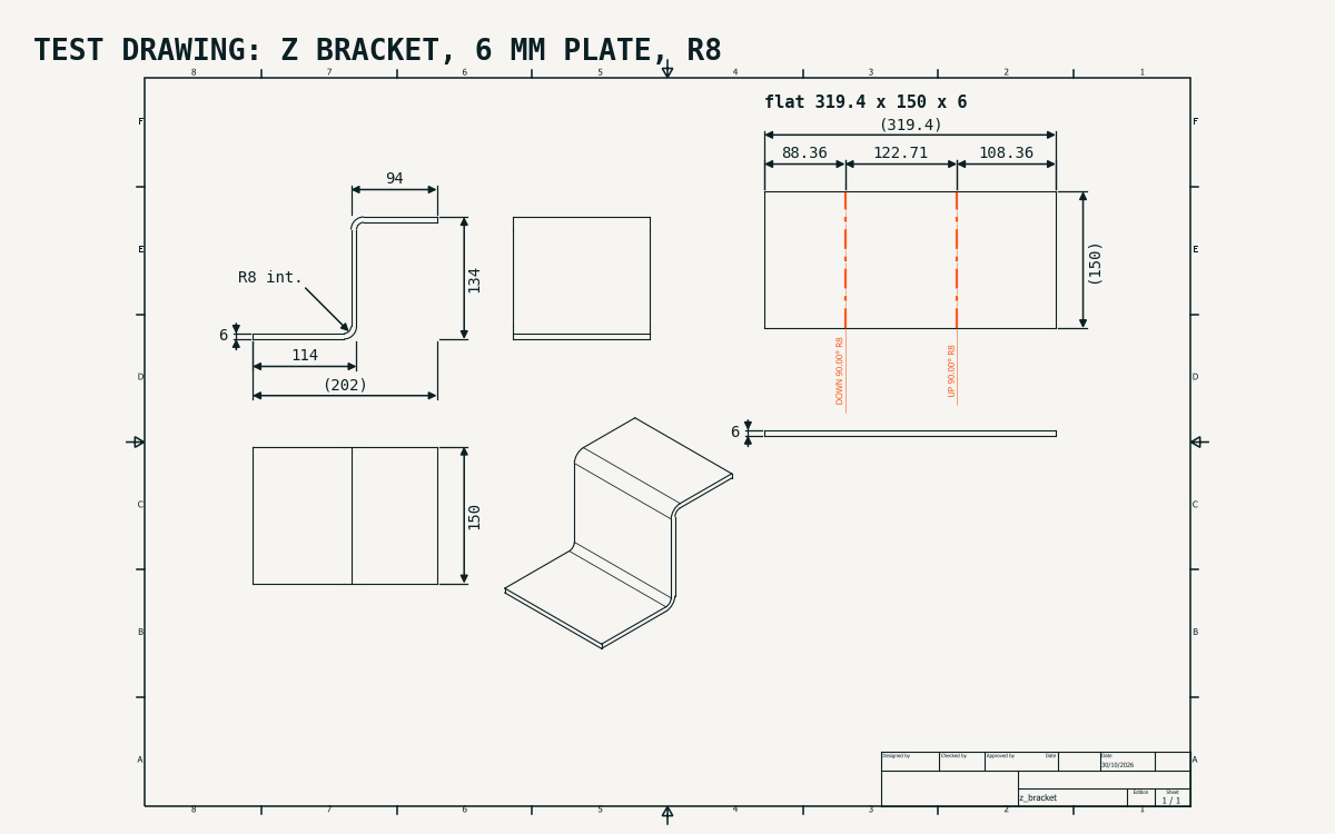
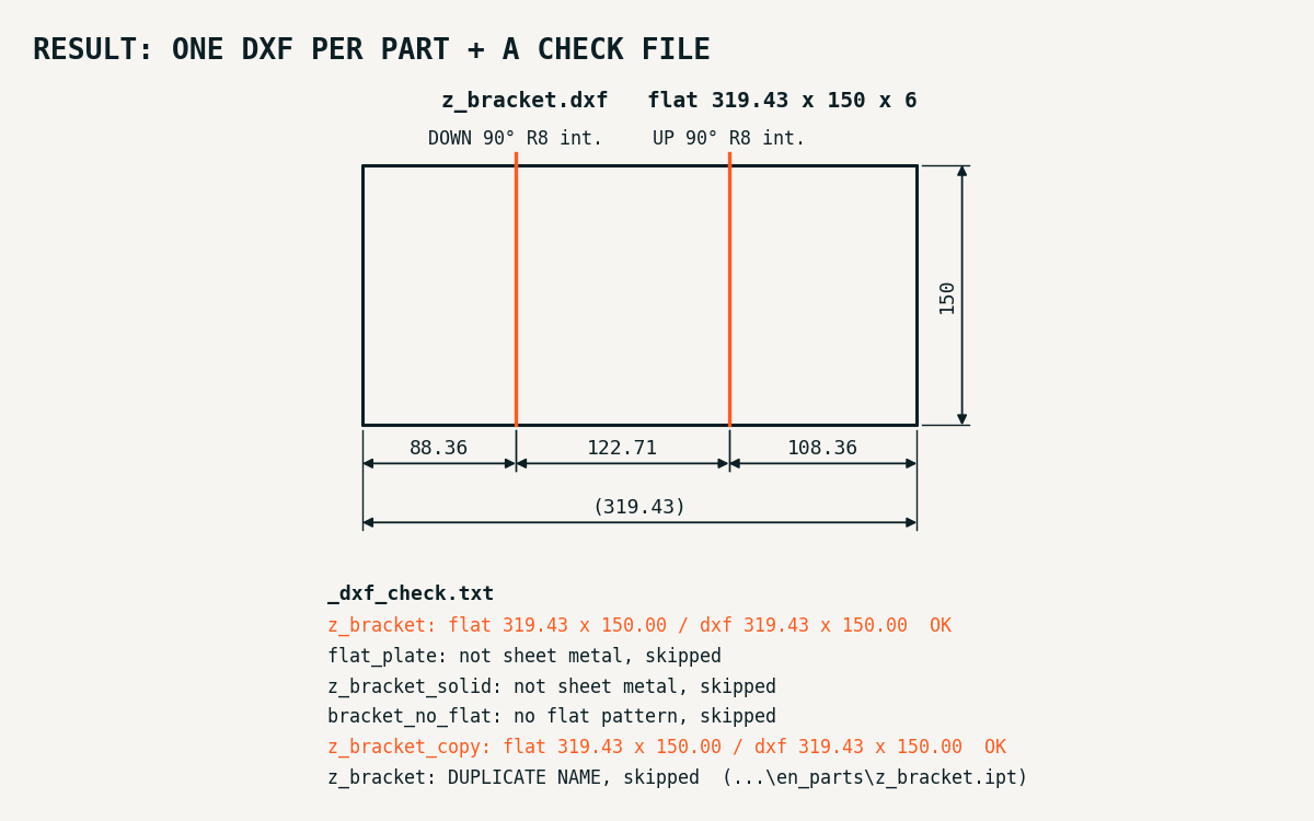
We ran the rule on this page as an iLogic rule in Inventor 2025.2 on a test assembly we built for it. The assembly has two copies of our Z test bracket (6 mm plate, R8 inside radius, flat 319.43 × 150 mm). It also has one bracket without a flat pattern, two parts that are not sheet metal, and a copy of a bracket with the same file name in another folder. The images are redrawn from the DXF files of these runs. In the two drawing images, the first and the last, the dimensions are drawn on the image (the drawing we exported has none) and the decimal commas of Inventor's bend notes are shown as points; in the first the author field of the title block is blanked, in the last the border and title block are left out. In the check file image the numbers are shown with decimal points (our PC uses commas, so the real file says 319,43) and the path in the last line is shortened.
This came up on the Autodesk forum: How to export 1:1 DXF files for sheet metal and fabrication. Our answer there has an earlier version of this rule. This page is the long answer.
The rule
' Run in the assembly. For every sheet metal part with a flat pattern:
' writes a DXF of the flat pattern (model space, no drawing, no view scale)
' and checks the DXF size against the flat pattern size.
' Output: a new folder DXF_<date_time> next to the assembly (old DXF are never overwritten)
' + _dxf_check.txt with one line per part.
' The check compares each DXF with its own flat pattern: it can't tell if the flat pattern is out of date.
Sub Main()
    Dim dxfFormat As String = "FLAT PATTERN DXF?AcadVersion=R12"   ' CHANGE: add options here, see the table
    Dim tolerance As Double = 0.05                                 ' CHANGE: allowed difference in mm
    Dim oAsm As AssemblyDocument = ThisDoc.Document
    Dim outFolder As String = System.IO.Path.GetDirectoryName(oAsm.FullFileName) & "\DXF_" & Now.ToString("yyyyMMdd_HHmmss")   ' CHANGE if you want another folder
    System.IO.Directory.CreateDirectory(outFolder)
    Dim report As New System.Text.StringBuilder()
    Dim usedNames As New System.Collections.Generic.HashSet(Of String)(StringComparer.OrdinalIgnoreCase)

    For Each oDoc As Document In oAsm.AllReferencedDocuments
        If oDoc.DocumentType <> DocumentTypeEnum.kPartDocumentObject Then Continue For
        Dim partName As String = System.IO.Path.GetFileNameWithoutExtension(oDoc.FullFileName)
        ' two parts with the same file name in different folders would give the same DXF name
        If Not usedNames.Add(partName) Then
            report.AppendLine(partName & ": DUPLICATE NAME, skipped (" & oDoc.FullFileName & ")")
            Continue For
        End If
        If oDoc.SubType <> "{9C464203-9BAE-11D3-8BAD-0060B0CE6BB4}" Then
            report.AppendLine(partName & ": not sheet metal, skipped")
            Continue For
        End If
        Dim oSM As SheetMetalComponentDefinition = oDoc.ComponentDefinition
        If Not oSM.HasFlatPattern Then
            report.AppendLine(partName & ": no flat pattern, skipped")
            Continue For
        End If
        Try
            Dim dxfPath As String = outFolder & "\" & partName & ".dxf"
            oSM.DataIO.WriteDataToFile(dxfFormat, dxfPath)

            ' flat pattern size in mm (API lengths are in cm)
            Dim flatA As Double = Math.Max(oSM.FlatPattern.Length, oSM.FlatPattern.Width) * 10
            Dim flatB As Double = Math.Min(oSM.FlatPattern.Length, oSM.FlatPattern.Width) * 10
            ' DXF size from the $EXTMIN / $EXTMAX header
            Dim ext() As Double = DxfExtents(dxfPath)
            Dim dxfA As Double = Math.Max(ext(2) - ext(0), ext(3) - ext(1))
            Dim dxfB As Double = Math.Min(ext(2) - ext(0), ext(3) - ext(1))

            Dim ok As Boolean = Math.Abs(flatA - dxfA) < tolerance And Math.Abs(flatB - dxfB) < tolerance
            report.AppendLine(partName & ": flat " & flatA.ToString("0.00") & " x " & flatB.ToString("0.00") & _
                " / dxf " & dxfA.ToString("0.00") & " x " & dxfB.ToString("0.00") & If(ok, "  OK", "  CHECK THIS ONE"))
        Catch ex As Exception
            report.AppendLine(partName & ": ERROR " & ex.Message)
        End Try
    Next

    System.IO.File.WriteAllText(outFolder & "\_dxf_check.txt", report.ToString())
End Sub

' Returns minX, minY, maxX, maxY read from the DXF header.
' InvariantCulture: the DXF always uses a dot, a PC with comma decimals would misread it.
Function DxfExtents(dxfPath As String) As Double()
    Dim lines() As String = System.IO.File.ReadAllLines(dxfPath)
    Dim ext(3) As Double
    Dim inv As System.Globalization.CultureInfo = System.Globalization.CultureInfo.InvariantCulture
    For i As Integer = 0 To lines.Length - 5
        Dim key As String = lines(i).Trim()
        If key = "$EXTMIN" Then
            ext(0) = Double.Parse(lines(i + 2).Trim(), inv)
            ext(1) = Double.Parse(lines(i + 4).Trim(), inv)
        ElseIf key = "$EXTMAX" Then
            ext(2) = Double.Parse(lines(i + 2).Trim(), inv)
            ext(3) = Double.Parse(lines(i + 4).Trim(), inv)
        ElseIf key = "ENDSEC" Then
            Exit For
        End If
    Next
    Return ext
End Function
What to change:
dxfFormat: what goes in the DXF. The table below shows what each option did on our test bracket.tolerance: the allowed difference between DXF and flat pattern, 0.05 mm.outFolder: every run makes a newDXF_<date_time>folder next to the assembly, so DXF files you already sent or edited by hand are never overwritten. In our run an oldz_bracket.dxfin aDXFfolder next to the assembly stayed as it was.- The GUID: leave it. It is the sheet metal part subtype.
Where to paste it: open the assembly, Manage > iLogic > Add Rule, give it a name, paste, Save & Run. To start it from a script instead: run an iLogic rule from outside Inventor.
The rule writes files and nothing else: it does not unfold parts, it does not save them. A part without a flat pattern is skipped and listed. To make the flat pattern of a bent part that came in from STEP as a plain solid, see iLogic flat pattern from a STEP solid.
What the check catches, and what it doesn't
The rule reads the DXF size from the $EXTMIN / $EXTMAX header and compares it with FlatPattern.Length and Width, which the API gives in centimetres. On the test bracket both said 319.43 × 150 mm. We also measured the geometry in both DXF files with a separate DXF reader (ezdxf): 319.43 × 150, the same.
- Same file name, two folders: the second part is skipped and listed as
DUPLICATE NAME. Without this check, both parts would get the same DXF file name. - Comma decimals: the DXF header writes numbers with a dot. The rule reads them with
InvariantCulture, so it works on a PC set to commas (ours is). - Out-of-date flat pattern: the check can't see it, because it compares the DXF with the flat pattern as it is now. We did not test this case. After a change to a part, make sure its flat pattern is current before you run the rule.
- Other export options: we ran the rule with the R12 string above. For the four strings in the next table we read the header of each DXF the same way: 319.43 × 150 in all four, so the check would say OK.
What the export options put in the DXF
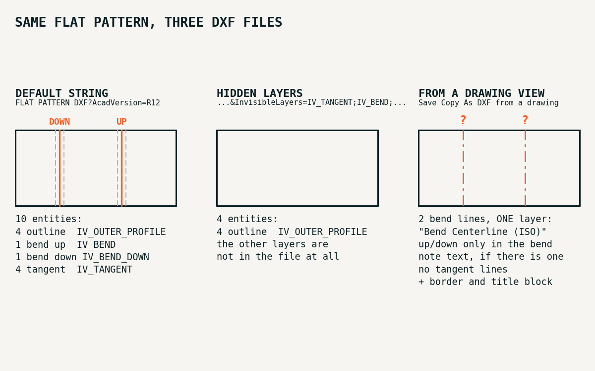
Same flat pattern, four strings, each file opened and counted:
| String | What is in the DXF |
|---|---|
FLAT PATTERN DXF?AcadVersion=R12 |
10 entities: outline, 4 lines (IV_OUTER_PROFILE); bend up, 1 line (IV_BEND); bend down, 1 line (IV_BEND_DOWN); tangent lines, 4 (IV_TANGENT). No units in the header; the numbers are mm. |
...&InvisibleLayers=IV_TANGENT;IV_BEND;IV_BEND_DOWN;... |
4 entities: the outline only. The hidden layers are not turned off: they are not in the file. |
FLAT PATTERN DXF?AcadVersion=2018&MergeProfilesIntoPolyline=True |
The outline is 1 polyline instead of 4 lines. Bend and tangent lines as above. Units set to mm in the header. |
...&OuterProfileLayer=CUT&InteriorProfilesLayer=CUT&BendUpLayer=BEND_UP&BendDownLayer=BEND_DOWN |
The same 10 entities, on layers CUT, BEND_UP, BEND_DOWN. The tangent lines stay on IV_TANGENT. |
The full InvisibleLayers list we used: IV_TANGENT;IV_BEND;IV_BEND_DOWN;IV_TOOL_CENTER;IV_TOOL_CENTER_DOWN;IV_ARC_CENTERS;IV_FEATURE_PROFILES;IV_FEATURE_PROFILES_DOWN;IV_ALTREP_FRONT;IV_ALTREP_BACK;IV_ROLL_TANGENT;IV_ROLL;IV_UNCONSUMED_SKETCH_CONSTRUCTION. Holes go on IV_INTERIOR_PROFILES (Autodesk's default layer name), which is not in the list. Our test bracket has no holes, so we did not see that layer in our files.
All the options and their default layer names are on Autodesk's page Translate - Sheet Metal to DXF. Which layers your cutting software wants is a question for whoever programs the machine. For an exporter with layer colours and names, Jelte de Jong has Dxf export made easy.
A DXF saved from the drawing
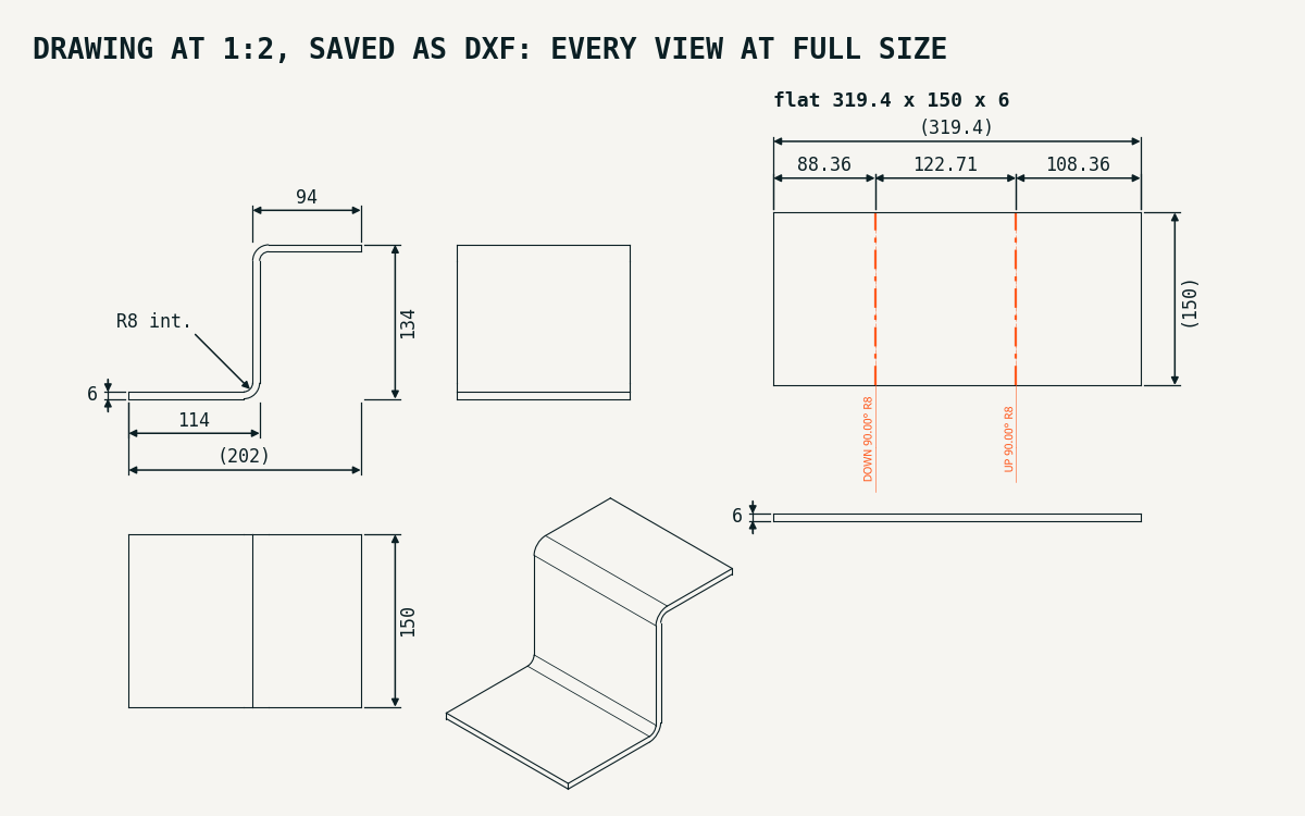
We also put the bracket in drawings and saved them as DXF with the DXF translator's Save Copy As, called from the API with no export options set (Inventor 2025.2). First the flat pattern alone, once at 1:1 and once at 1:2. Then a full A2 drawing at 1:2: front, top and side view of the bent part, an isometric view, the flat pattern with Inventor's bend notes (we moved them below the part), and its edge view. What came out:
- The size was right. The flat pattern was 319.43 × 150 also from the 1:2 views, and in the full drawing the front view was 202 × 134, the real size. Inventor scaled the border and title block by 2 instead: the sheet in the file is 840 × 594 for the A3 and 1188 × 840 for the A2, both doubled.
- Up or down is only in the text. Both bend lines are on one layer,
Bend Centerline (ISO). The direction is in the file only as the text of the bend notes ("DOWN 90,00° R8", "UP 90,00° R8" in ours), so only if the drawing has them. The direct export keeps the lines onIV_BENDandIV_BEND_DOWN. - No tangent lines on the flat pattern.
- The border, the title block and every view are in the file, together with the flat pattern.
So in this test the scale was right, and the bend direction was there only as note text. We did not test the export dialog by hand: with other export settings the result can be different.
Questions people ask
Does it work on a single part?
Yes, the same WriteDataToFile line works on the part's sheet metal definition. For the table above we called it on the part, from a script.
Can it write DWG?
Autodesk documents FLAT PATTERN DWG as well. We did not test it.
What do I do with the DXF next? Nest them on your sheets: nesting cut parts on steel sheets from DXF profiles. How we make DXF files from a STEP: STEP to DXF cutting files.