Blog · Inventor · 1 Nov 2026 · Last updated 2 Nov 2026 · 5 min read · By Stefano B.
Change the Inventor drawing line color and weight of one component with iLogic
One iLogic rule moves every line of one component, in every view of the sheet, to a copy of its layer with your color and weight, one call per layer. Hidden lines stay dashed, and a second run changes nothing. In Inventor 2025.1 and later there is also a one-line way to change the color only.
Short answer: to change the Inventor drawing line color and weight of one part or sub-assembly, collect its line segments with DrawingView.DrawingCurves(occurrence), copy their layer with your color and weight, and move them all at once with Sheet.ChangeLayer. If you only need the color and you have Inventor 2025.1 or later, DrawingView.SetComponentLineColor does it with one call per view.
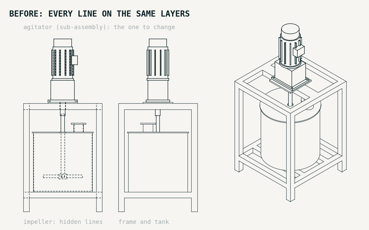
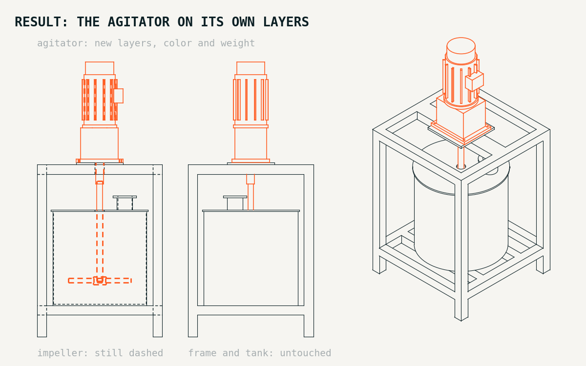
We ran the code on this page as iLogic rules in Inventor 2025.2. The example is a machine we modelled for it, a tank agitator: a welded frame in 60x60 tube, 800 x 800 and 1100 mm high, a 600 mm tank with a lid and a nozzle, and on top the agitator, a sub-assembly of gearbox, motor, shaft and impeller that reaches down into the tank. The sheet has 3 views: front with hidden lines (the impeller inside the tank), side, and isometric. The job: make the agitator stand out in every view, red and thicker, and leave the rest of the machine as it is. The images are redrawn from the DXF of that sheet after the rule: orange is the new layers (red in the drawing). The "before" image is the same DXF with every line drawn in ink. Line weight does not show in the images; the numbers below check it. For the times we also used a much bigger test sheet, further down.
The rule
Paste it as a rule in the drawing and change the first lines.
' Moves every line of one component (part or sub-assembly, at any level) to its own layer, in every view of the active sheet.
' Sheet.ChangeLayer moves a whole collection in one call, instead of editing the curves one by one.
' Each original layer (visible, hidden...) gets its own copy, so hidden lines stay dashed.
Dim sOccPath As String = "AGITATOR:1"   ' CHANGE: component as shown in the assembly browser; if it sits inside
                                        ' another sub-assembly, the whole path with "/", e.g. "MIXER:1/AGITATOR:1"
Dim iRed As Integer = 255            ' CHANGE: line color (red, green, blue 0-255)
Dim iGreen As Integer = 0
Dim iBlue As Integer = 0
Dim dWeightCm As Double = 0.07       ' CHANGE: line weight in cm (0.07 = 0.7 mm)
Dim sSuffix As String = " - " & sOccPath.Replace("/", " > ")   ' new layers: "<original layer> - <component path>"

Dim oDrawDoc As DrawingDocument = ThisDoc.Document
Dim oSheet As Sheet = oDrawDoc.ActiveSheet
Dim oColor As Inventor.Color = ThisApplication.TransientObjects.CreateColor(iRed, iGreen, iBlue)
Dim oGroups As New Dictionary(Of String, ObjectCollection)
Dim aPath() As String = sOccPath.Split("/"c)
Dim iCount As Integer = 0

For Each oView As DrawingView In oSheet.DrawingViews
    Dim oOcc As ComponentOccurrence = Nothing
    Dim oCurves As DrawingCurvesEnumerator = Nothing
    Try
        Dim oAsmDoc As AssemblyDocument = oView.ReferencedDocumentDescriptor.ReferencedDocument
        oOcc = oAsmDoc.ComponentDefinition.Occurrences.ItemByName(aPath(0))
        For i As Integer = 1 To aPath.Length - 1   ' walk down the path, one level at a time
            Dim oNext As ComponentOccurrence = Nothing
            For Each oSub As ComponentOccurrence In oOcc.SubOccurrences
                If oSub.Name = aPath(i) Then
                    oNext = oSub
                    Exit For
                End If
            Next
            If oNext Is Nothing Then Throw New Exception(aPath(i) & " not found")
            oOcc = oNext
        Next
        oCurves = oView.DrawingCurves(oOcc)
    Catch
        Continue For   ' view of another model, or the component is not in this view
    End Try
    For Each oCurve As DrawingCurve In oCurves
        For Each oSeg As DrawingCurveSegment In oCurve.Segments
            Dim sLayer As String = oSeg.Layer.Name
            If sLayer.EndsWith(sSuffix) Then Continue For   ' already moved by an earlier run
            If Not oGroups.ContainsKey(sLayer) Then
                oGroups.Add(sLayer, ThisApplication.TransientObjects.CreateObjectCollection)
            End If
            oGroups(sLayer).Add(oSeg)
            iCount += 1
        Next
    Next
Next

For Each sLayer As String In oGroups.Keys
    Dim oNewLayer As Layer = Nothing
    Try
        oNewLayer = oDrawDoc.StylesManager.Layers.Item(sLayer & sSuffix)
    Catch
        oNewLayer = oDrawDoc.StylesManager.Layers.Item(sLayer).Copy(sLayer & sSuffix)
    End Try
    oNewLayer.Color = oColor
    oNewLayer.LineWeight = dWeightCm
    oSheet.ChangeLayer(oGroups(sLayer), oNewLayer)
Next

Logger.Info(iCount & " line segments of " & sOccPath & " moved to " & oGroups.Count & " layer(s)")
What to change:
sOccPath: the component as it shows in the assembly browser. If it sits inside another sub-assembly, write the whole path with/, likeMIXER:1/AGITATOR:1. We tested it on a sub-assembly at the top level and on one a level down: all its parts moved with it.iRed,iGreen,iBlue: the color.dWeightCm: the line weight in centimetres (0.07 cm = 0.7 mm). Pick a weight heavier than your visible lines, or the change will not show.
What we measured
- 303 line segments of the agitator moved in the 3 views: 113 in the front view, 67 in the side view, 123 in the isometric view.
- Hidden lines stay dashed. In the front view 40 segments of the agitator were on the hidden-line layer, about half of them the shaft and the impeller inside the tank: they moved to its own copy, with the same dashed line type.
- Color and weight read back: both new layers return red (255, 0, 0) and 0.07 cm.
- Only that component changes. The frame and the tank kept every line on the original layers, in all 3 views.
- A second run changes nothing: 86 layers before and after, every segment where it was.
- Time: the rule took 3.2 s on this sheet, rule start included.
- A bigger sheet: an agitator has a few hundred lines, but a big assembly can have thousands. For the times we built a test sheet with 10,410 segments to move: a sub-assembly of 60 plates with 80 holes each, placed twice (SUB_A:1 and SUB_A:2), plus one other part, in the same 3 views.
- Times on that sheet: the rule took 29.9 s. Setting color and weight curve by curve took 132.4 s. Same session, rule start included in both.
- Where the time goes: in a run with a timer inside the rule (38.5 s in all), 25.1 s went into reading the segments, the rest into the new layers and the
ChangeLayercalls. - Same checks on the big sheet: hidden lines, the untouched SUB_A:2 and the second run gave the same results as on the agitator sheet.
- One level down: the same sub-assembly inside another assembly (FRAME.iam in the test) placed twice, with
sOccPath = "FRAME:1/SUB_A:1". 10,410 segments moved in 27.6 s. The SUB_A:1 inside FRAME:2, with the same name, and the other part in both frames kept every line, and a second run changed nothing.
Why a layer, and not each curve
Each DrawingCurve has its own Color and LineWeight, so you can set them one by one. That works (we read the color back), but it is one change per curve: 132.4 s against 29.9 s on the big sheet. Sheet.ChangeLayer takes the whole collection in one call. It has been in the API since Inventor 2011, according to the Autodesk help.
Inventor 2025.1 and later: color only, one call per view
Inventor 2025.1 added DrawingView.SetComponentLineColor (Autodesk help). It sets the line color of one component in a view, and nothing else: no line weight, no layer.
' Inventor 2025 and later: one call per view sets the line color of one component (color only, not the weight).
Dim sOccName As String = "AGITATOR:1"   ' CHANGE: component name as shown in the assembly browser (top level)
Dim oDrawDoc As DrawingDocument = ThisDoc.Document
Dim oColor As Inventor.Color = ThisApplication.TransientObjects.CreateColor(255, 0, 0)   ' CHANGE: color
Dim iViews As Integer = 0

For Each oView As DrawingView In oDrawDoc.ActiveSheet.DrawingViews
    Try
        Dim oAsmDoc As AssemblyDocument = oView.ReferencedDocumentDescriptor.ReferencedDocument
        oView.SetComponentLineColor(oAsmDoc.ComponentDefinition.Occurrences.ItemByName(sOccName), oColor)
        iViews += 1
    Catch
        ' view of another model, or the component is not in this view
    End Try
Next

Logger.Info(sOccName & " recolored in " & iViews & " view(s)")
On the agitator sheet it ran in 0.35 s, rule start included (0.16 s on the big sheet). The sheet showed the agitator in red in all 3 views, and the frame and tank unchanged. The layers did not change (84 before and after), and GetComponentLineColor on the view returns the red. On the big sheet the curves kept their own color property: the view returns the red, the curves do not, and no curve of SUB_A:2 turned red. So if you need the weight too, or you have an older Inventor, use the layer rule above.
References
More drawing work by code: dimension styles in Inventor with scripts and auto balloons in assembly drawings. How we make complete drawings from a STEP: fabrication drawings from STEP files.